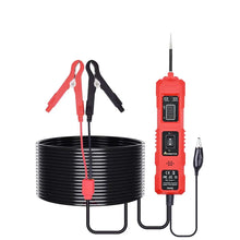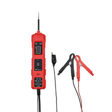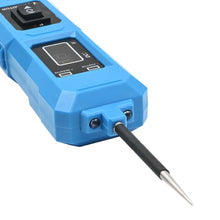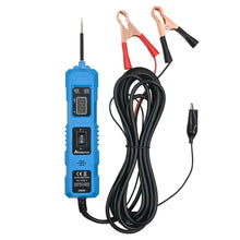
SPECIFICATIONS
Brand Name: aermotor
Hign-concerned Chemical: None
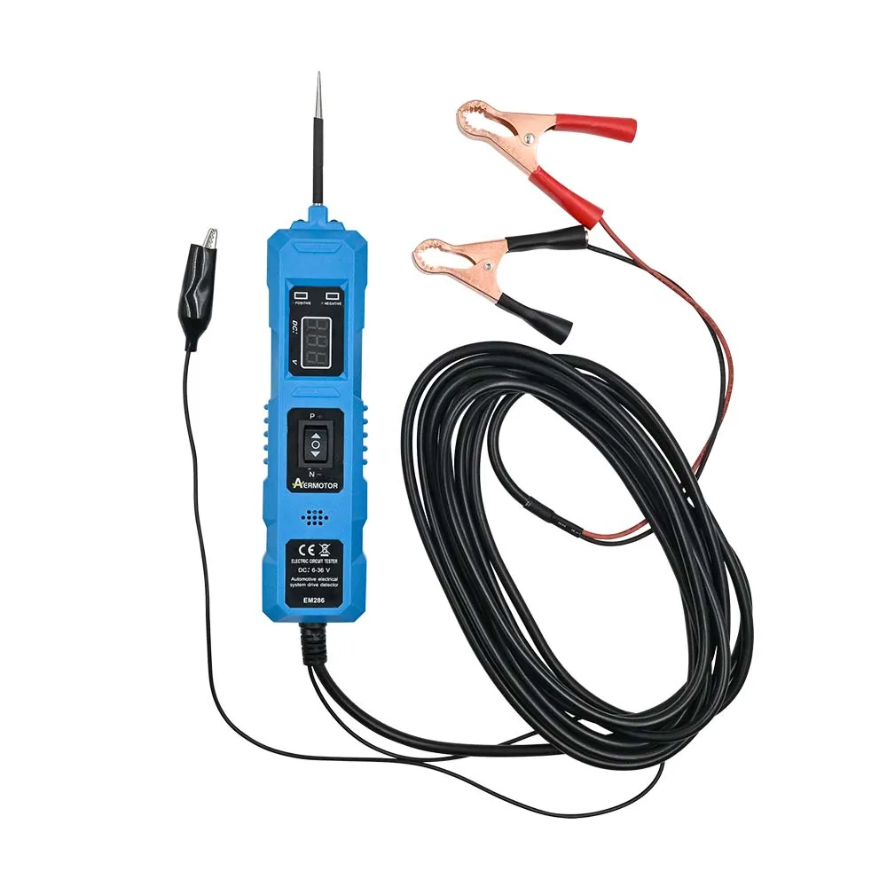
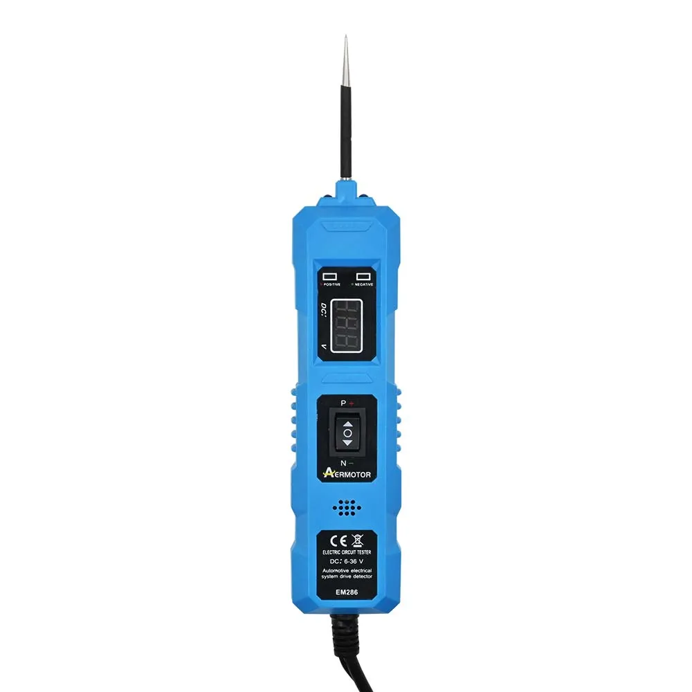
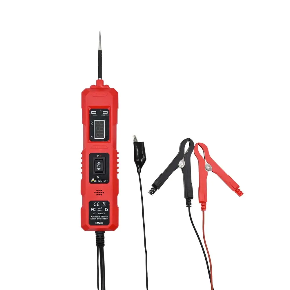
Universal 6V-36V/48V Automotive Electric Circuit Tester Car Electrical System Tester Voltage Power Probe Kit LED Digital Display

describe:
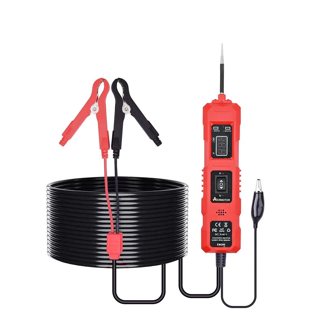
Circuit tester, automotive circuit tester with voltage display LED light, automotive power circuit probe kit suitable for 6-48V DC
characteristic:
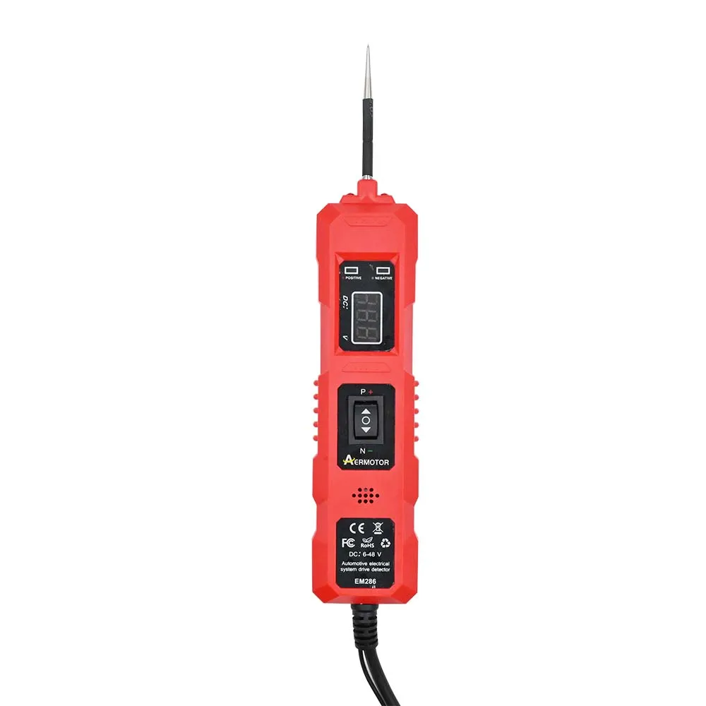
Accurate voltage measurement: This circuit tester is capable of measuring DC voltages ranging from 6V to 48V. Its precise digital display ensures more accurate readings than other ordinary voltage testers, making it an essential tool for reliable and accurate vehicle electrical diagnosis.
Overload protection: When the current exceeds 8A, the car probe circuit tester has an automatic cut-off function to ensure safe and reliable use, protecting users and vehicles from potential damage.
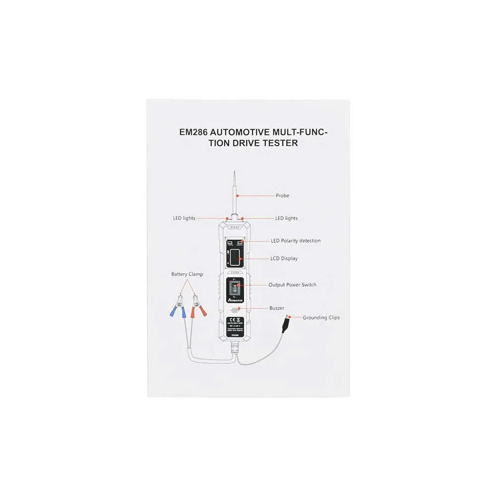
Built in buzzer and LED light: The probe tester is equipped with an integrated buzzer and LED light, making it easy and convenient to use even in low light or dark conditions.
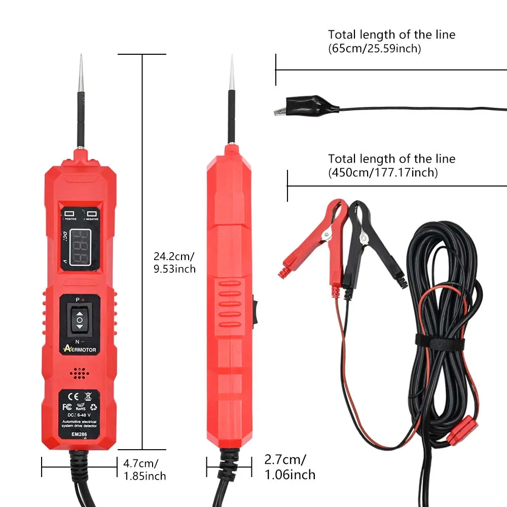
Extend cable length: The tester is equipped with a 4.5-meter-long cable, which can be flexibly tested from the front to the rear of the vehicle without constantly searching for a suitable vehicle grounding.
Widely used: Automotive circuit testers provide a wide range of testing functions, from continuity and voltage polarity testing to tracking short circuits and checking ground contacts.
usage method:
1.) Unplug the connecting wire of the tester.
2.) The red clip is connected to the positive pole of the battery, and the black clip is connected to the negative pole of the battery; At this time, the blue number displays the current battery voltage value and turns on the headlights; Reverse connection, does not display voltage value, but the light is still on;
1: Self inspection
Before using the tester, please perform a self check to display the integrity of the device.
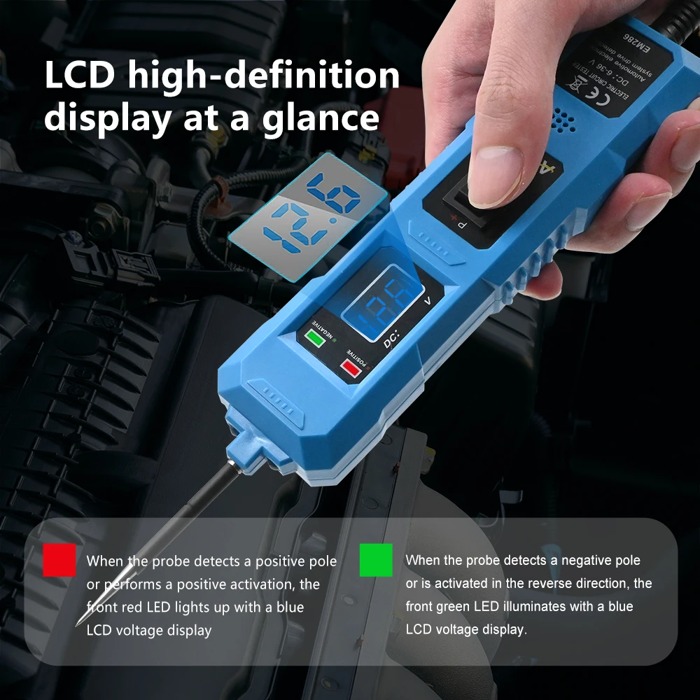
Press the button of the tester to the (▲) position, and the LED on the instrument will light up in red, indicating that the probe is outputting positive voltage.
After pressing the button of the tester to the () position, the LED on the instrument lights up green, indicating that the probe outputs negative voltage.
3.) Release the button and make contact between the probe of the tester and the positive terminal of the battery. At this point, the LED on the instrument lights up in red, indicating that there is a positive voltage at the measuring node.
4.) Release the button and connect the probe of the tester to the negative terminal of the battery. The LED on the instrument will light up green, indicating that there is negative voltage at the measuring node.
5.) Press the button on the tester to the (▲) position, and the LED on the tester will light up red. Quickly contact the probe with the negative terminal of the battery (note that a small spark may be generated), and the LED on the tester will change from red to green, and the buzzer will sound.
2. Use polarity detection
1.) Contact the probe of the tester with the contact point of unknown polarity of the battery to be tested. If the LED on the instrument lights up red, it means that the tested contact point has a positive voltage; If the LED on the instrument lights up green, it indicates that the tested contact has a negative voltage;
3. On off test
1. Use an auxiliary grounding small black clip to clamp one end of the tested wire of the tester, connect the tester probe, and place the tester probe in contact with the other end of the tested wire. If the LED on the instrument lights up green, it indicates that the tested wire is in a connected state;
If the green LED on the tester does not light up, it indicates that the tested wire is in a disconnected state;
4. Test components (offline)
1.) Use the auxiliary grounding wire black clamp on the tester to clamp the negative terminal of the tested component
The auxiliary grounding wire is connected to
Press the button on the tester to the negative pole of the bulb
Probe connected to the positive pole of the bulb
Position: At this time, the LED on the instrument lights up red, and the tester probe presses the switch to connect to the positive terminal of the tested component and make it work; If the LED on the instrument changes from red to green and the buzzer sounds,
Disconnect the test and immediately check whether the components are in good working condition or whether the required working current of the components is caused by the overload power supply of the tester.
5. Detection components (online)
If the tested component is on the positive pole (negative pole with iron) of the UOTOA front end, press the tester button to the (▲) position. At this time, the instrument LED will light up red, and the tester probe will contact the positive pole of the tested component to make it work.
If the tested component is at the negative terminal of UOTOA, press the tester button back to the (V) position. At this time, the instrument LED will light up green, and the tester probe will contact the negative terminal of the tested component to make it work.
When components are divided into several small parts (such as lighting) and it is necessary to test the contact position of each small part corresponding to the socket used, the contact position of the repaired component can be removed from the linked socket,
Use a small black clamp with auxiliary grounding on the tester to clamp the common ground terminal of the component. Press the tester button to the (▲) position, and the LED on the instrument will light up red. Use a probe to contact the metal point on the connector to make the component work.
If the indicator light on the instrument changes color and emits a buzzing sound when ringing, the test should be immediately disconnected to check whether the components have reached the required working current for normal operation or whether the components are caused by overload power supply of the tester.
6. Jumper operation
The large black clamp on the tester is physically fixed to the auxiliary grounding clamp, and users can disconnect the original circuit connection (such as control switch or circuit breaker) to connect the circuits of the two black clamps of the tester for testing and maintenance.
NOTOR
7. Grounding test
For some components such as motors, the negative pole needs to be well grounded to cope with high current flow. This tester can test the grounding integrity of the components.
2.) Press the () position on the tester, and the LED on the instrument will light up red. The test probe has a positive pole and contacts the negative pole of the component (the position with iron on the negative pole), as close as possible to one end of the component. Fused amplifier
When the grounding is good, the LED on the instrument turns green and the buzzer emits a beep sound. If the grounding is poor or the measuring contact is not on the ground, the LED will still be red and the+buzzer will not sound.
Red 6V-48V:

Blue 6V-36V


